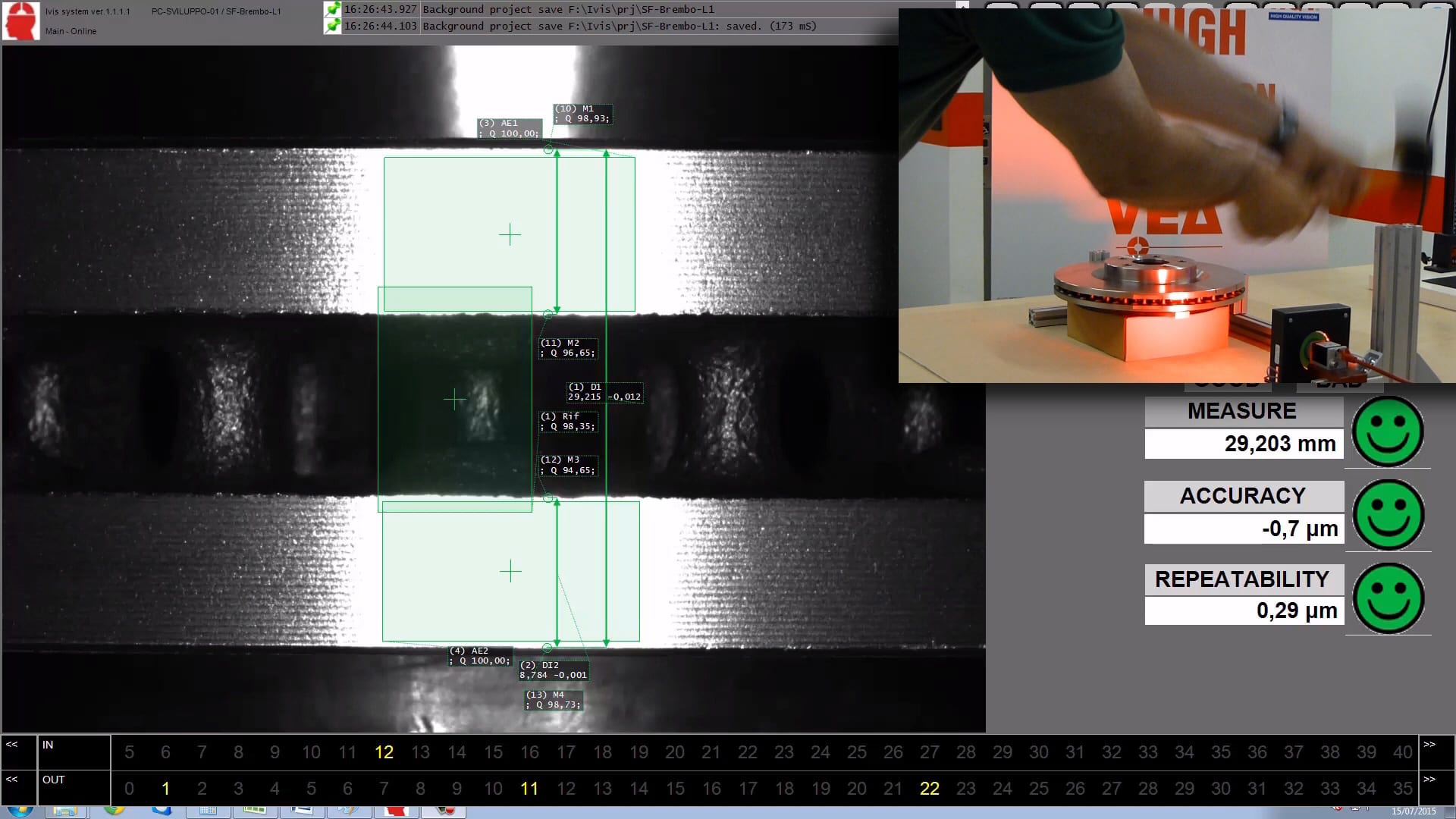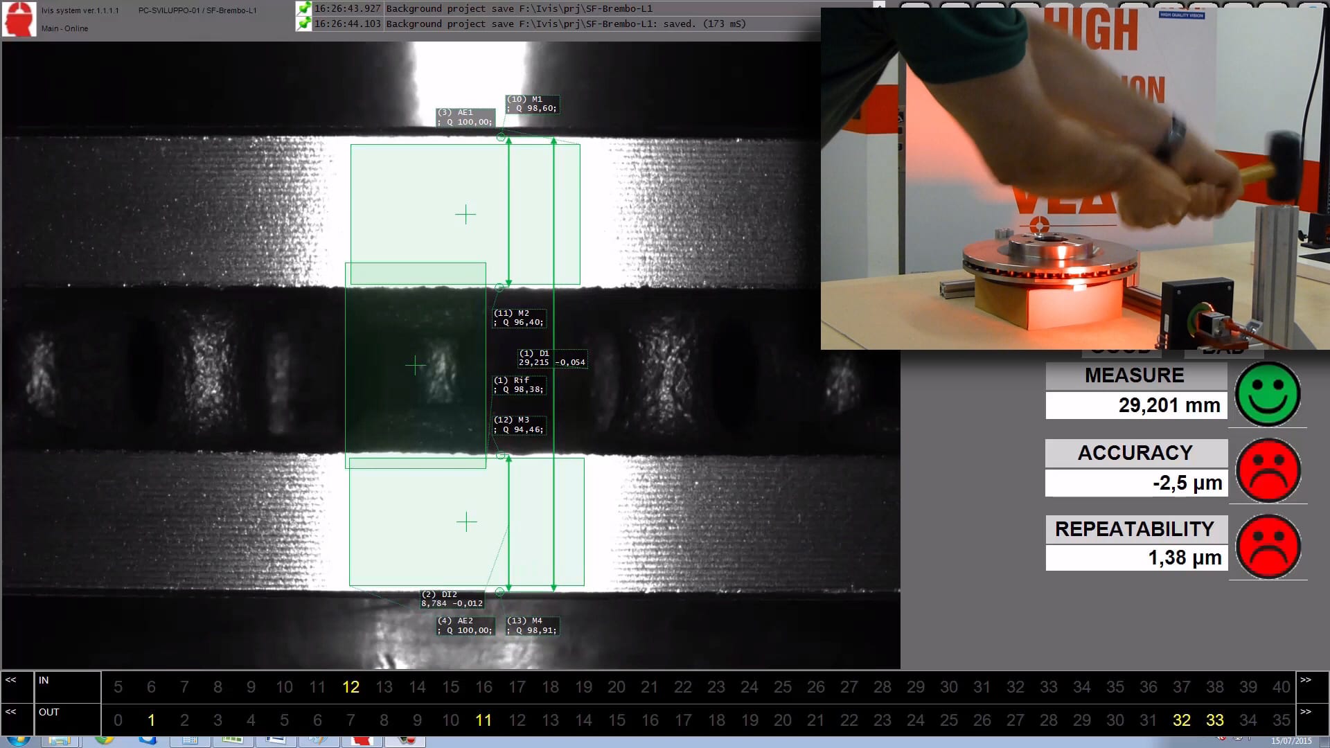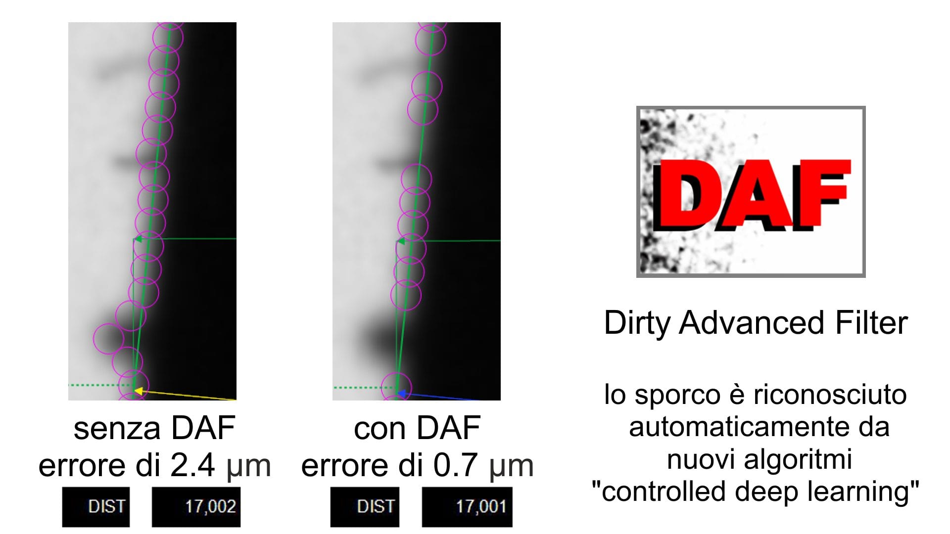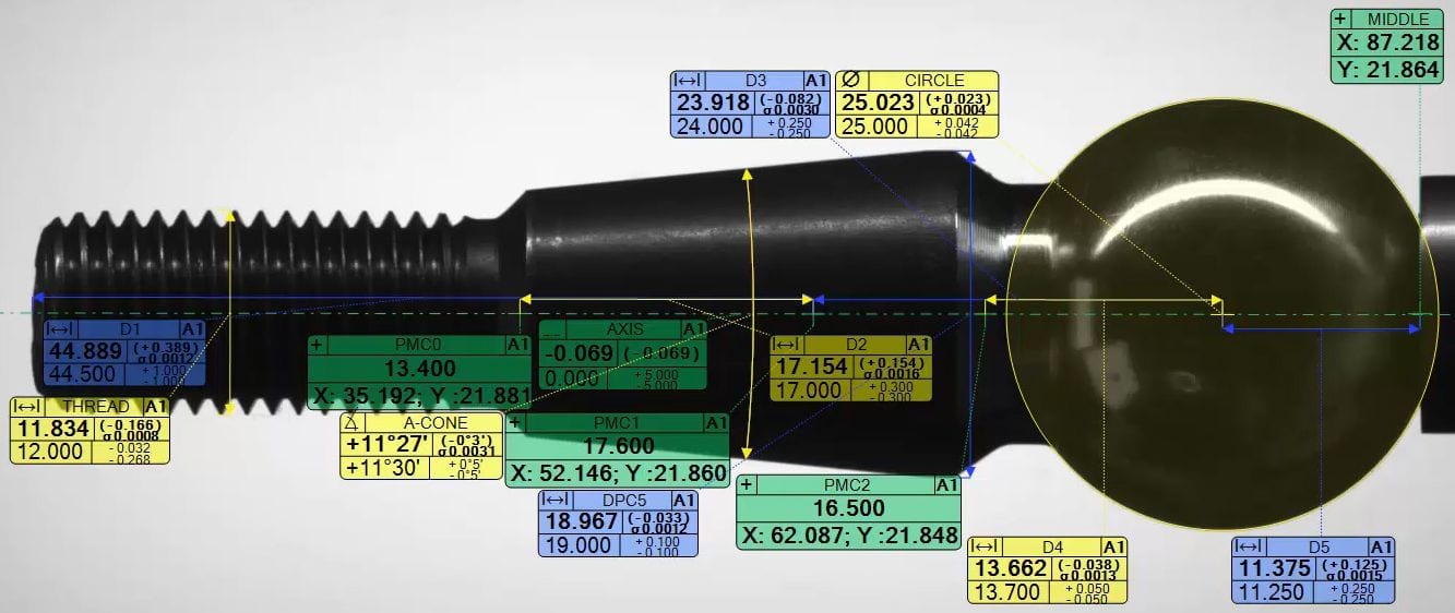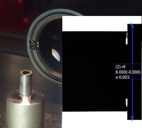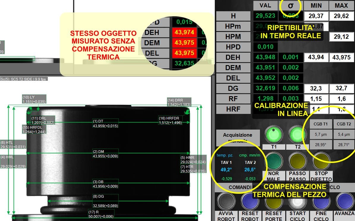
- Thermal compensation
- Vibration stabilization
- Real-time repeatability and accuracy check
- Digital dirt removal
- Micrometric accuracy
PRECISE MEASUREMENT IN INDUSTRY: LABORATORY METROLOGY PRECISION IN THE PRODUCTION ENVIRONMENT
Obtaining a precise and fast measurement in a production environment is a reality of industry 4.0 that makes a company really competitive on an international level.
In recent years, quality control and measurement of 100% of manufacturing production is increasingly required.
For many industrial sectors, there is an increasing need to ensure that all products comply with the specifications, encouraging a migration from manual to automatic quality control. The demand for reliability of the product in PPM (Parts Per Million) , makes the statistical sample control carried out in the laboratory insufficient.
On the other hand, the practical application of metrology has always found its natural home in a controlled environment, the laboratory. The instrumentation and technologies designed to perform measurements have adapted to this environment, in fact the simple adaptation of these instruments to the production environment often generates reliability problems.
Leaving the laboratory and entering the factory directly with fast and reliable controls is only possible using new technologies. The main purpose is to obtain a fast micrometric measurement in a production environment, therefore in an uncontrolled environment.
To better identify this technological field, the neologism has recently been created".Metrotronics", the result of the union of metro(logia) and (mecca)tronica.
The term Metrotronics was born from the need to identify a series of actions, thoughts, rules and technologies that represent the adaptation of metrological instruments so that they can operate directly and effectively in an industrial production environment.
"THE METROLOGICAL LAB IN THE FACTORY" is the philosophy behind this thought. It is necessary to be able to create fast and automatic measuring systems for industry, with the same precision that we would have in a metrology laboratory.
Below is a brief comparison to better understand the reasons for the difference of technologies in the laboratory and in the industrial environment.
Advantages of metrology in the production environment: precise measurement in an industrial environment, reliable, fast and repeatable
- measures all the parts in an industrial environment.
- automatic measurement is constant in the evaluation.
- measurement in industry reduces the number of rejects due to the latency time of the periodic inspection in the laboratory.
- reduces the time needed to set up production facilities.
- measurement information can be directly and in real time backdated to the production facilities.
- measurement in an industrial environment has a higher reliability than spot-checking.
- reduces the cost of lack of quality.
- measuring directly in the production environment allows objective and immediate feedback.
- The measure's drift information is useful for preventive maintenance.
- increases the quality and value of the product
- enhances the corporate image.
Metrological laboratory precision in production environment
TEMPERATURE: LTC (Laboratory Thermal Compensation)
One of the main causes of loss of measurement accuracy in an industrial environment is due to thermal expansion.
For example an object of 42 mm aluminium has a coefficient of expansion of 1 micron for each degree centigrade, so to obtain a correct measurement it is necessary to know the temperature of the instrumentation, of the environment and of each single object to be measured.
The LTC module, allows to obtain the same accuracy that you would have in a metrology laboratory (20° ±1°) even in production environments with temperature range between 10° and 60° by means of 4 stages of detection.
In just 2 hundredths of a second up to 4 temperature sources are analyzed and compensated for.
1) the ambient temperature
2) the temperature of the piece
3. the temperature of the gauge in line
4) the temperature of the measuring instrument
VIBRATION: MSA (Micro Stabilized Accuracy)
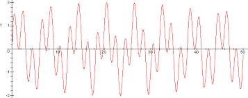
The production environment is not free from vibrations of various kinds and these affect the measurement repeatability of the instruments significantly.
In fact, a large part of today's instrumentation does not provide information on the reliability of the measurement at the moment in which it is performed, so in case of vibration it is possible that an incorrect measurement is detected even by instruments that are correctly calibrated.
The Micro Stabilized Accuracy (MSA) module analyzes the type of vibration and provides a reliable measurement value.
The MSA algorithm calculating the repeatability in real time establishes how measurable the part is. In this way you get the confidence that the measurement is correct in the production environment, which is impossible with other instruments. If a situation of poor repeatability is detected, for example, the measurement can be repeated.
IPER-RESOLUTION: XVR2 (Extended Virtual Resolution 2)
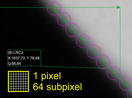
Sub-resolution techniques allow to increase the resolution of a camera, generating a matrix of subpixels (in this case 8 x 8) using different technologies.
Through "controlled deep learning" subpixels are generated from the analysis of adjacent pixels based on pre-acquired models. In metrology, particularly reliable learning models are used, cross-checked to prevent inaccurate information from being generated, hence the expression "controlled deep learning".
Another technology that is used in these micrometers is the "pixel shifting", the subpixels are generated by the analysis of sequential images taken at different times and positions.
All these technologies allow us to achieve the remarkable resolution of 750 Mpixel.
BELOW THE MICRON
When optically measuring objects with resolutions below the micron, we encounter problems related to the wavelength of light. One of these is the "speckle" effect that is highlighted by illuminating an object with a monochromatic light source (with a laser the effect is also evident to the naked eye).
The monochromatic light can be recognized by its clear red, green or blue colour.
It is observed that the transmitted light is not distributed, but is composed of peaks of intensity on a dark background. This effect further influences the measurement repeatability and it is for this reason that we use a particular staggered polychromatic illumination where the single wavelengths of which it is composed are not multiple. The staggered polychromatic light can be recognized by its white coloration.
The type of material to be measured, its colouring and surface finish can generate small inaccuracies. Hence the need to create a series of algorithms capable of compensating for this situation.
CLEANING: DAF (Dirty Advanced Filter)
Finding clean parts in the production environment is not a foregone conclusion, but essential to optimize measurement in industry. The electronic DAF (Dirty Advanced Filter) allows to detect the presence of both solid and liquid foreign bodies.
Dirt that is recognized as such is filtered out, improving measurement accuracy.
If the amount of dirt is such that the measurement is unreliable, the algorithm evaluates the actual measurability of the part which may generate a preventive deviation or a request for subsequent measurement after mechanical cleaning.
POSITIONING CORRECTION
Automatic systems do not always have the possibility to position parts precisely, also to reduce handling times, so in order to obtain precise measurements it is necessary for the system to calculate the axis of the part automatically and precisely.
Workpiece axis generation is configurable and allows all dimensions to adapt. There is the possibility to generate more than one axis.
AUTO-CALIBRATION
A measuring instrument that provides inaccurate values is always a generator of insidious problems. Measuring systems in industrial environments are often more susceptible to changes in accuracy.
The VEA micrometers allow you to perform automatic calibration or at least notice an incorrect calibration. Two calibration modes can be chosen.
Real-time auto-calibration by reference placed in the field of view.
Periodic multi-master auto-calibration (up to 20) in which all calibration parameters are adjusted on a series of reference masters.
The masters can be loaded manually or automatically.
Metrological tests
Our instruments have performed very strict tests both in the laboratory and in an industrial environment.
As a comparison we have performed the tests including and excluding the compensation systems described above.
| 6 | 6 mm | ± 0,4 μm | ± 0,05 μm | ± 0,7 μm | ± 0,13 μm |
| 12 | 12 mm | ± 0,6 μm | ± 0,06 μm | ± 0,9 μm | ± 0,15 μm |
| 18 | 18 mm | ± 0,9 μm | ± 0,08 μm | ± 1,2 μm | ± 0,16 μm |
| 26 | 26 mm | ± 1,2 μm | ± 0,09 μm | ± 1,5 μm | ± 0,18 μm |
| 36 | 36 mm | ± 1,5 μm | ± 0,11 μm | ± 1,9 μm | ± 0,20 μm |
| 42 | 42 mm | ± 1,8 μm | ± 0,12 μm | ± 2,2 μm | ± 0,21 μm |
| 48 | 48 mm | ± 2,0 μm | ± 0,13 μm | ± 2,4 μm | ± 0,22 μm |
| 56 | 56 mm | ± 2,3 μm | ± 0,15 μm | ± 2,7 μm | ± 0,24 μm |
| 64 | 64 mm | ± 2,6 μm | ± 0,17 μm | ± 3,1 μm | ± 0,26 μm |
| 72 | 72 mm | ± 2,9 μm | ± 0,2 μm | ± 3,4 μm | ± 0,3 μm |
| 80 | 80 mm | ± 3,2 μm | ± 0,2 μm | ± 3,7 μm | ± 0,3 μm |
| 90 | 90 mm | ± 3,5 μm | ± 0,2 μm | ± 4,2 μm | ± 0,3 μm |
| 100 | 100 mm | ± 3,9 μm | ± 0,2 μm | ± 4,6 μm | ± 0,3 μm |
| 110 | 110 mm | ± 4,3 μm | ± 0,3 μm | ± 5,0 μm | ± 0,4 μm |
| 120 | 120 mm | ± 4,6 μm | ± 0,3 μm | ± 5,4 μm | ± 0,4 μm |
| 136 | 136 mm | ± 5,2 μm | ± 0,3 μm | ± 6,1 μm | ± 0,4 μm |
| 150 | 150 mm | ± 5,8 μm | ± 0,3 μm | ± 6,7 μm | ± 0,4 μm |
| 170 | 170 mm | ± 6,5 μm | ± 0,4 μm | ± 7,5 μm | ± 0,5 μm |
| 190 | 190 mm | ± 7,2 μm | ± 0,4 μm | ± 8,3 μm | ± 0,5 μm |
| 216 | 216 mm | ± 8,2 μm | ± 0,5 μm | ± 9,4 μm | ± 0,6 μm |
| 240 | 240 mm | ± 9,1 μm | ± 0,5 μm | ± 10,4 μm | ± 0,6 μm |
| 268 | 268 mm | ± 10,1 μm | ± 0,6 μm | ± 11,6 μm | ± 0,7 μm |
| 300 | 300 mm | ± 11,3 μm | ± 0,6 μm | ± 12,9 μm | ± 0,8 μm |
(1) measured value with glass calibration scale with 25 ±2σ measurements
(2) measured value with calibrated plug size class 1 from 60% to 70% of the field of vision with 25 measurements ±2σ
VIDEO GALLERY
specifications may change without notice


